Below the video that prove my circuit is functioning.
NAME : Siti Nur Adila binti Azman | ID : 51216111040 | PROJECT SUPERVISOR : Sir Mohd Syazwan Md Yid
Sunday, 19 January 2014
Week 11 (FYP 2)
Alhamdulillah, finally the circuit functioning well. This is because, I forget to placed the EMG ground. The picture shows the result that I got.
Week 10 (FYP 2)
Alhamdulillah. Finally, I found the electrode. Actually it is from my friend, who had ordered it from eBay.
Week 9 (FYP 2)
For this week, my circuit still not functioning. But I continue to search electrode, because it is difficult to find the right electrode in Malaysia.
Week 7 (FYP 2)
This week I continue testing my circuit at the LAB 209 with guidance from Sir Syazwan and Sir Zubir. Unfortunately, my circuit did not functioning. I need to troubleshoot the circuit for the next week until the circuit is functioning well.
Week 3 (FYP 2)
Last week, I managed to buy some components for my circuit. I had bought all components of my circuit. This is the place that I bought the component, recommended by Sir Syazwan.
Week 2 (FYP 2)
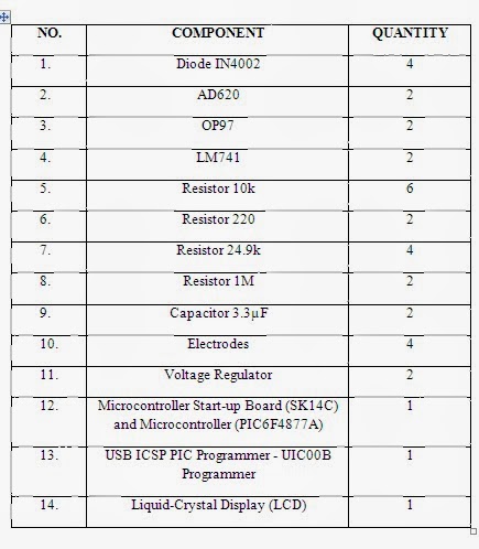
This is the circuit that I am going to construct. The table below show the component that I am going to use to construct it. This component for two circuits.
Week 1 (FYP 2)
For the first week of semester September, I proceed with construct the circuit. Start searching and buying the component.
Monday, 15 April 2013
Week 10 (Presentation Day)
ASSESSORS
- Sir Hisham bin Mohd Desa
- Madam Naszariah Mohd Noor
Sunday, 14 April 2013
Monday, 4 March 2013
Week 6
After a few weeks searching for the best electrodes, Alhamdulillah, finally I have found the best electrodes or EMG sensors. Surface EMG Sensor from Delsys are fulfill the criteria that we want to this project.
Through my reading, I understanding of the design of the Delsys Surface EMG Sensors is crucial for the proper use. The first concept to consider is that the sensors rely on differential amplification. This means that the signal is detected at two sites, the signals are subtracted, and the difference is amplified. As a result, any signal that is “common” to both detection sites will be removed, and signals that are different at the two sites will be amplified. Most noise is “common” to both detection sites and is removed. The desired surface EMG signal is different at the two sites and is amplified. In the double differential model, the signal is detected at three sites and the subtraction procedure is performed twice to allow even greater focus on
the desired
muscle and to eliminate crosstalk.
The second
concept to consider is the fixed parallel bar arrangement of the skin contacts.
Muscle fibers run longitudinally in a muscle. As a result, the electrical
activity of the muscle also propagates predominantly along the length of the
muscle. Each Delsys EMG Sensor has an arrow on top that should be aligned along
the length of the muscle so that the parallel bar detection sites transect the
muscle fibers. The parallel bar arrangement, in contrast to circular contacts,
ensures that a maximum number of muscle fibers are monitored in a given
location. The fixed distance between the contacts ensures that measurements
are reproducible since changes in the distance between detection surfaces would
affect the detected signal.
Figure 1 : Electrode
Week 5
For this project, Sir recommended me to use PIC16F877A. Using USB ICSP PIC Programmer V2010 (UIC00B) and Enhanced 40 pins PIC Start-Up Kit (SK40C)
Figure 1 : PIC16F877A
Figure 2 : PIC16F877A Data Sheet
Figure 3 : UIC00B
UIC00B is designed to program popular Flash PIC Microcontroller which includes most of the PIC family. Besides 8bit, it can also program 16bit and 32bit PIC MCU. On board ICSP (In Circuit Serial Programming) connector offers flexible methods to load program.USB port is commonly available and widely used on Laptop and Desktop PC, thus is very convenient to use UIC00B. It offers reliable, high speed programming and free windows interface software.
Figure 4 : SK40C
SK40C is a 40pin PIC microcontroller starter kit designed to offer a easy-to-start solution for PIC microcontroller user. This board comes with basic element for user to begin project development.
Figure 5 : Example of Tutorial for PIC16F877
For PIC16F877A, UIC00B and SK40C, I need to install MPLAB IDE and PICkit software, to run the program. Then, I to try the SK40C 16F877A sample program, LED Blinking.I had learned that with the correct code, we can run the program.
From the last meeting, Sir have explain about the program. First, we need to write a program in MPLAB IDE using C language. But for my first try, I used the sample program. Next, I run the program and verified. If the program is fail, we need to check the program and do some correction. If the program is successful, then we can import the program to PICkit software. Connect the UIC00B and SK40C. Before we import the hex file, we need to check the communication, whether the connection with the device are correct. If the connection with the device are right, then we can import the program. Next, run the program. Tadaaa..!! The LED BLINKING. Yeyyy..!!!
Figure 6 : LED BLINKING
For the next task, I need to try the PIC by using LCD (Liquid Crystal Display). Sir give a task to make a program that related to my project using the similar program. Examples, when we push the switch button (SW1), the LCD will show "RIGHT". When we push the switch button (SW2), the LCD will show "LEFT".
Thursday, 14 February 2013
Week 4
Before mid term break, we have decided to use surface electrode. Below are the advantages and disadvantages between surface electrodes and fine wire electrodes.
SURFACE ELECTRODES
|
FINE WIRE ELECTRODES
|
|
ADVANTAGES
|
|
|
DISADVANTAGES
|
#cross talk is the recording of activity from a muscle, other than the one under investigation at the recording site |
|
Wednesday, 13 February 2013
Week 3
Next task, I need to find a variety of EMG circuit design so that we can compare and make reference for this project.
[1]
From this schematic designed circuit,Danny Ng do mentioned disposable surface electrode are used to pick up the signal. He did an amplifier and signal conditioning circuit. Above, I attached the schematic designed of Danny Ng.
The amplitude of the signal pick up is low, so amplification is needed to measure the detected signal. A differential amplifier is needed because of the high common mode rejection ratio (CMRR). Two electrodes are connected in between the region of interest and the ground electrode is connected to a reference point. A driven feedback is implemented in the design to improve the signal quality. Second order active low pass and active high pass filter are used to further amplify the signal and filter off the unwanted part of the signal.A low-pass filter is an electronic filter that passes low-frequency signals and attenuates (reduces the amplitude of) signals with frequencies higher than the cutoff frequency. For high-pass filter, is an electronic filter that passes high-frequency signals but attenuates (reduces the amplitude of) signals with frequencies lower than the cutoff frequency.
As the design uses single supply, a 5v to -5v converter is used to power the active amplifier. Isolation amplifier and supply isolation is added as some basic safety implementation in the circuit.
Isolation amplifiers provide electrical isolation and an electrical safety barrier. They protect data acquisition components from common mode voltages, which are potential differences between instrument ground and signal ground. Instruments that are applied in the presence of a common mode voltage without an isolation barrier allow ground currents to circulate, leading in the best case to a noisy representation of the signal under investigation. In the worst case, assuming that the magnitude of common mode voltage or current is sufficient, instrument destruction is likely. Isolation amplifiers are used in medical instruments to ensure isolation of a patient from power supply leakage current.
Figure 2 : The Signal detected from the electrode when the muscle are moved
[2]
Figure 3 : EMG Analysis Circuit
The following circuit was designed and built to test the
overall surface EMG system (electrodes & amplifier).
[3]
Week 2
Research about the EMG electrodes. The EMG signal is measured either non-invasively with surface electrodes or invasively with wire or needle electrodes. Since typical EMG signal levels are in the region of 400 μV to 3 mV (depending on many factors), the measured EMG signal is almost always pre-amplified, amplified.
EMG can be recorded from the skin surface or by placing an electrode directly within the subject’s muscle. This is usually referred to as a fine-wire recording. Surface EMG is generally recorded with either passive or active electrodes placed on the intact skin surface over the belly of the subjects muscle, while fine-wire recordings use a wire electrode that is inserted into the muscle by a trained (and, in most cases, licensed) professional. Each electrode type has specific advantages and disadvantages.
Examples of EMG electrodes :
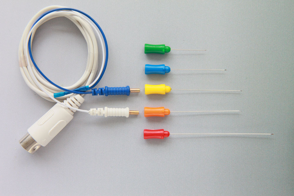
Figure 1 : Connection Method of Disposable EMG Monopolar Needle Electrodes
Figure 2 : Surface EMG Electrodes
Thursday, 31 January 2013
Week 1
Do some research about what is exactly EMG. The basic function of the machine, how to use the machine, the procedure, the results whether normal or abnormal and etc.
EMG (Electromyography) is used for recording the electrical activity of the muscles when these cells contract and also when the cells are at rest. EMG can be measured by applying conductive elements or electrodes to the skin surface, or invasive within the muscle. Electromyography is a test that measures and records the activity of contracting muscles in response to electrical stimulation. It checks the health of the muscles and the nerves that control the muscles. EMG is performed using an instrument called electromyogaph, to produce a record called an electromyogram.
Measuring and accurately representing the EMG signal depends on the properties of the electrodes and their interaction with the skin, amplifier design, and the conversion and subsequent storage of the EMG signal from analog to digital form.
The quality of the measured EMG is often described by the ratio between the measured EMG signal and unwanted noise contributions from the environment. The goal is to maximize the amplitude of the signal while minimizing the noise.
![]() |
| Figure 1 : EMG Machine |
Tuesday, 29 January 2013
Introduction
Title : Development of EMG Circuit for Controlling an Electric Wheelchair
Category : Healthcare
Synopsis : Developing an EMG circuit with the suitable sensor to control an electric wheelchair.Collection of data (voltage output from shoulders movement).Programming of the circuit using collected data
Subscribe to:
Posts (Atom)


.png)
.jpg)